Published: Jul-2026 | Category: Fun With Science
Can two pendulums help us visualise some of the ideas used in quantum physics?
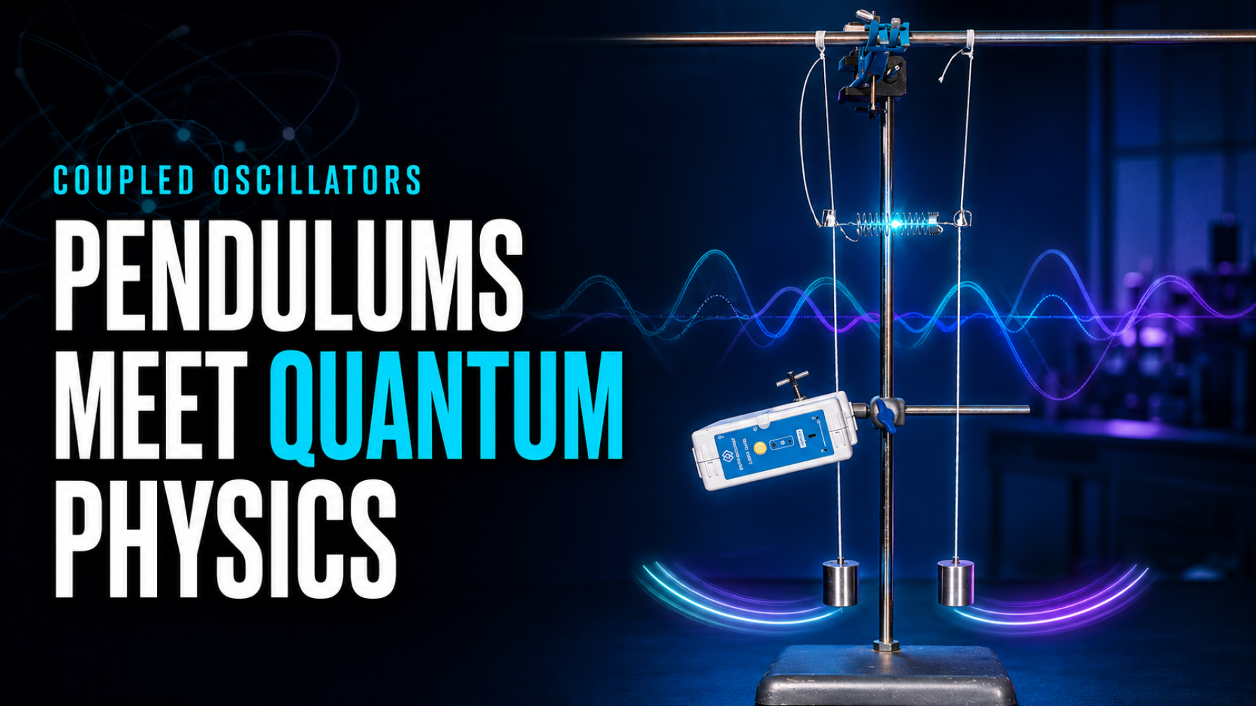
In this practical investigation, two identical pendulums are connected by a weak spring to create a pair of coupled oscillators. When one pendulum is displaced and released, its motion gradually decreases while the second pendulum begins to swing. The process then reverses, producing a repeating exchange of energy and a distinctive beat pattern.
Using a Data Harvest Wireless Light Gate Sensor with EasySense, students can measure the oscillations, explore normal modes and investigate how the position of the spring changes the rate of energy transfer. Although the pendulums remain entirely classical, their behaviour provides an accessible analogy for interacting quantum states.
An oscillator is a system that repeatedly moves backwards and forwards around an equilibrium position. A pendulum is a familiar example: gravity provides the restoring force that pulls the bob back towards its lowest point.
When two oscillators are connected, the motion of one can influence the other. In this experiment, a weak spring provides the coupling. As one pendulum moves, the spring applies a changing force to the second pendulum, allowing energy to pass between them.
Initially, one pendulum may have almost all the visible motion while the other is nearly stationary. As time passes:
This motion is not caused by energy disappearing and reappearing. Energy is continually exchanged through the coupling spring, while some is also gradually dissipated by air resistance, friction at the pivots and movement within the spring.
Before connecting the two pendulums, students can investigate the period of a single pendulum. For a small angular displacement, its theoretical period is:
T = 2π√(L/g)
Here, T is the period, L is the effective pendulum length and g is the acceleration due to gravity.
The equation predicts that the period is proportional to the square root of the length:
T ∝ √L
Increasing the pendulum length should therefore increase the time taken for each oscillation. Plotting T² against L should produce an approximately straight-line relationship. The gradient can also be used to calculate an experimental value for g.
This first investigation establishes the behaviour of each pendulum independently before the spring introduces an additional interaction.
A pair of identical coupled pendulums has two normal modes. These are special patterns in which the entire system oscillates at a single frequency.
In the symmetric mode, both pendulums move together in the same direction. The distance between the suspension strings changes very little, so the spring experiences relatively little stretching or compression.
In the antisymmetric mode, the pendulums move in opposite directions. The spring repeatedly stretches and compresses, adding an extra restoring effect and producing a slightly higher normal-mode frequency.
If only one pendulum is initially displaced, the resulting motion is a superposition of these two normal modes. Because their frequencies are slightly different, they move in and out of phase. This creates the changing amplitudes and repeating energy transfer observed in the experiment.
The ordinary pendulum period is the time taken for one complete swing. The beat period is much longer: it describes the time associated with the gradual transfer of motion between the two pendulums.
The beat behaviour arises from the difference between the symmetric and antisymmetric normal-mode frequencies. A larger separation between these frequencies produces faster energy transfer and a shorter beat period.
Students should distinguish carefully between:
The position of the spring provides a convenient way to change the strength of the interaction. The distance from the suspension point to the spring attachment position is labelled c.
Moving the spring further from the pivot gives the spring greater leverage. This increases the coupling between the pendulums, so energy transfers more rapidly and the beat period decreases.
For weak coupling, the beat frequency is expected to vary approximately with the square of the attachment distance. The beat period should therefore follow an approximate inverse-square relationship:
Tbeat ∝ c−2
Students can test this empirical relationship by plotting the measured beat period against c, c−1 and c−2, then comparing the quality of the resulting fits.
The pendulums are classical objects: they have definite positions, follow Newton’s laws and can be observed without displaying genuinely quantum behaviour. However, the mathematics used to describe the coupled system has a similar structure to that used for many interacting quantum systems.
The analogy includes several useful connections:
This makes the apparatus a useful visual introduction to concepts that appear in molecular physics, coupled optical cavities and quantum computing. In coupled qubits, for example, an interaction allows quantum information to be shared between states using a related mathematical framework.
It is important not to suggest that the pendulums themselves are quantum. The model reproduces some of the mathematics of coupling, superposition and mode splitting, but it does not demonstrate every feature of quantum mechanics.
The pendulums do not reproduce:
The experiment is therefore best described as a classical analogy for a coupled two-state quantum system. It helps students build intuition before encountering the more abstract quantum model.
The changing amplitudes can be observed by eye, but accurate timing makes the behaviour much easier to analyse. A Light Gate detects an interrupt flag as the pendulum passes through its sensing region, providing repeatable timing data without relying on a handheld stopwatch.
In EasySense, students can configure a Timing experiment using Time at A and display the results as a graph and table. As the pendulum slows, the interrupt flag remains in the sensing region for longer. The timing data can therefore help students follow the changing motion and determine the period of the oscillations and beats.
The Light Gate can connect through Bluetooth or USB, allowing results to be collected and compared immediately. This gives students more time to concentrate on patterns, relationships and experimental uncertainty.
This investigation allows students to:
The Light Gate may need to be positioned at a slight angle so the interrupt flag passes through reliably throughout the pendulum’s motion. The apparatus should remain rigid and aligned while measurements are taken.
Using a small release angle is important because the familiar simple-pendulum equation assumes that sin θ ≈ θ when the angle is measured in radians.
With one pendulum initially displaced, the first bob should begin with a large amplitude while the second remains nearly stationary. The motion will then transfer across the spring until the second pendulum has the larger amplitude.
The amplitudes should continue to rise and fall in opposition, creating a repeating beat envelope. Moving the spring further from the pivots should strengthen the coupling and shorten the time needed for the motion to transfer between the pendulums.
Real results will not be perfectly symmetrical. The oscillations gradually decay because energy is dissipated, while small differences between the pendulum lengths, masses or release conditions can affect the transfer pattern.
The Light Gate provides precise timing, so the largest uncertainties are likely to come from the mechanical setup. These may include:
Repeating each measurement and averaging the results can reduce the influence of random variation. Students should also check that the two uncoupled pendulums have closely matched periods before beginning the coupled investigation.
Coupled oscillators appear throughout physics and engineering. The same broad principles can be used to understand:
A pair of pendulums cannot reproduce all the physics of these systems, but it provides a visible and measurable starting point for understanding how coupling can create new collective patterns of behaviour.
The Quantum Oscillators investigation includes the experimental method, data tables, analysis guidance, mathematical relationships, teacher notes and questions for students.
Find free practical science investigations in Practical Explorer
The Data Harvest Wireless Light Gate Sensor is designed to make accurate timing and motion measurements accessible in the classroom. It can be used for pendulums, dynamics, free fall, acceleration, collisions, Newton’s laws, kinetic energy and many other practical investigations.
Learn more about the Wireless Light Gate Sensor
Two pendulums connected by a spring form a simple mechanical system with surprisingly rich behaviour. Energy passes repeatedly between the oscillators, producing beat patterns that arise from the superposition of symmetric and antisymmetric normal modes.
By changing the spring position, students can investigate how coupling strength controls the rate of energy transfer. The Light Gate and EasySense turn this changing motion into accurate timing data that can be graphed, compared and evaluated.
Most importantly, the experiment provides a bridge between familiar classical mechanics and the mathematics of interacting quantum systems. The pendulums are not quantum objects, but their behaviour offers an intuitive way to introduce coupling, superposition, mode splitting and oscillatory state transfer before students meet these ideas in a more abstract form.
Take a look at the following articles from the same topic.